Clearing Out the Unfinished Project Backlog
By Stephen Newberry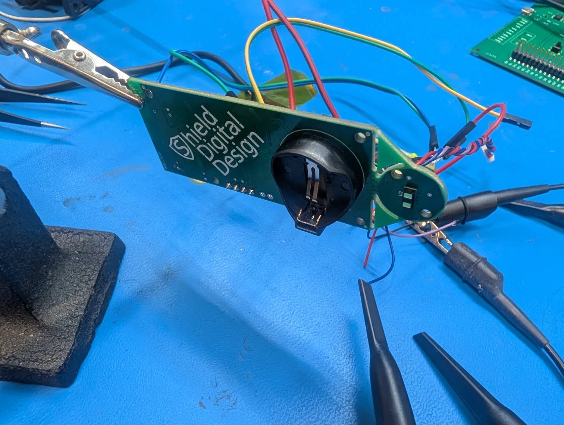
A popular engineering podcast1 asks their guests if they'd rather finish a project or start a dozen projects. Surely nobody starts any project without the intent to see it through to completion, but unfortunately, the realities of life often take over and thus we accumulate a shelf, box, or even garage full of unfinished projects. This describes me perfectly: I always have such high hopes for every project I begin, yet inevitably, the fun personal efforts fall victim to either massive scope reduction or complete abandonment.
Too often, my personal hurdle is the software: it's easy enough to get some hardware designed and built, but when it comes to writing the code, I can just never get started. This is one reason why I specifically designed my 10 Gbps USB switch to be hardware-only (i.e., programmed with solder). Imagine my delight when I realized that the powerful, new LLM tools are extremely capable at low-level firmware, at least capable enough to help me finish up some unfinished projects.
In today's article, I want to present my Oil Tank Monitor: a liquid-level sensor with Bluetooth connectivity to report the level remaining in my home heating oil tank. Here in the Northeast region of the United States, home heating oil is a popular fuel for the winter. I've always been diligent with logging the level in the tank by reading the gauge and writing it down in a paper log (thanks, U.S. Coast Guard, for instilling the habit of consistent logs). It's a bit of a manual process to transcribe the logs to CSV and plot the data to observe usage over time.
My paper logs are visible here along with my original on-tank gauge. The newly installed sensor is on the left.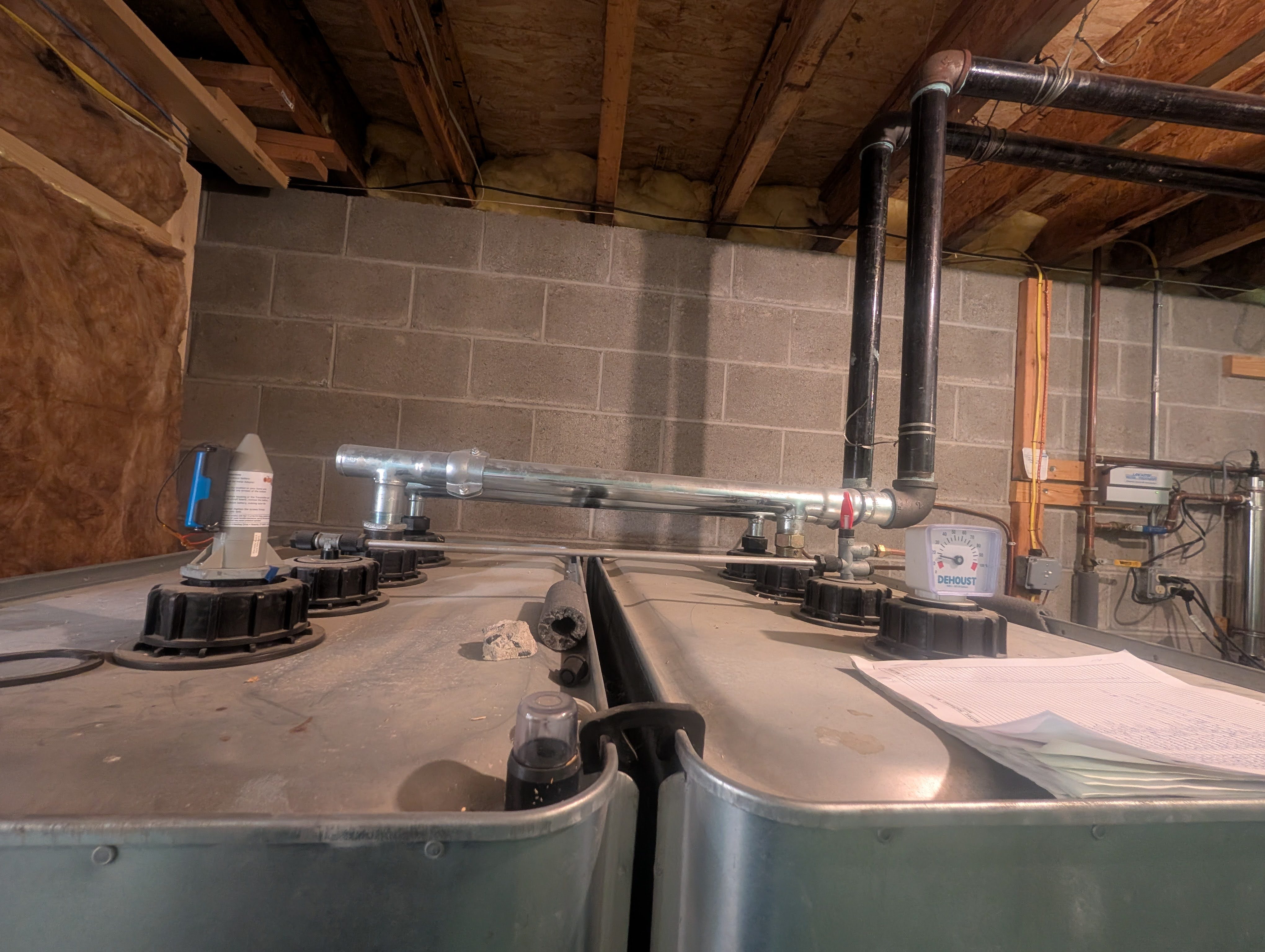
For my personal oil tank system, I have twin 275-gallon tanks in the basement connected together. I've got an analog gauge on top which reads percentage. I need to be able to measure oil level anywhere between empty and full in my system. I wanted to be able to check the level from my phone; if I were designing the hardware again in 2026, I would use Wi-Fi and have it sync tank level with a server so that I could easily check it even when away from the house. I still want to keep my CSV files for logging the level on my computer. I also need one other special feature: "fill mode". Back when we first bought the house, the oil tank whistles didn't work (these whistles are feedback during the fill process; when the whistle stops, the tank is full). I have since repaired the whistles, but part of the motivation behind "fill mode" was to be able to monitor the level at a rapid cadence during filling.
Back in 2018 (right in the middle of the IoT boom) I had the idea to create a connected device which checked the level using a time-of-flight sensor and could report it to a connected smartphone. The hardware came together pretty quickly: a Nordic Bluetooth-connected microcontroller coupled with a time-of-flight sensor.
After some research, I settled on the Nordic NRF52832 and the STMicro VL53L1X ToF sensor. As for the PCB size, I had a very specific reason for designing it as I did. My house originally had a wireless tank level sensor (well, the sender unit was on the tank; the receiver was nowhere to be found). That system, the "Rocket" wireless tank gauge2, was interesting but connected only to a standalone receiver. I decided to design my custom PCB to be able to reuse the original housing. The PCB was built as one piece, but mousebites allow the ToF sensor board to be disconnected from the main board. During development, the four required connections (power, ground and I2C signals) used PCB traces going from one board to the other. When I was ready to integrate with the housing, I disconnected the ToF board and used a custom-designed wire harness to connect the two boards. This process worked out wonderfully for my implementation.
I also had originally wanted to use a simple 2032 coin cell, but during testing I found that it was absolutely insufficient for the long battery life that I desired. While it may be ugly, since this is a one-off device, I decided to just fit an 18650 cell on the outside of the housing.
The PCB during development with the ToF sensor board still connected.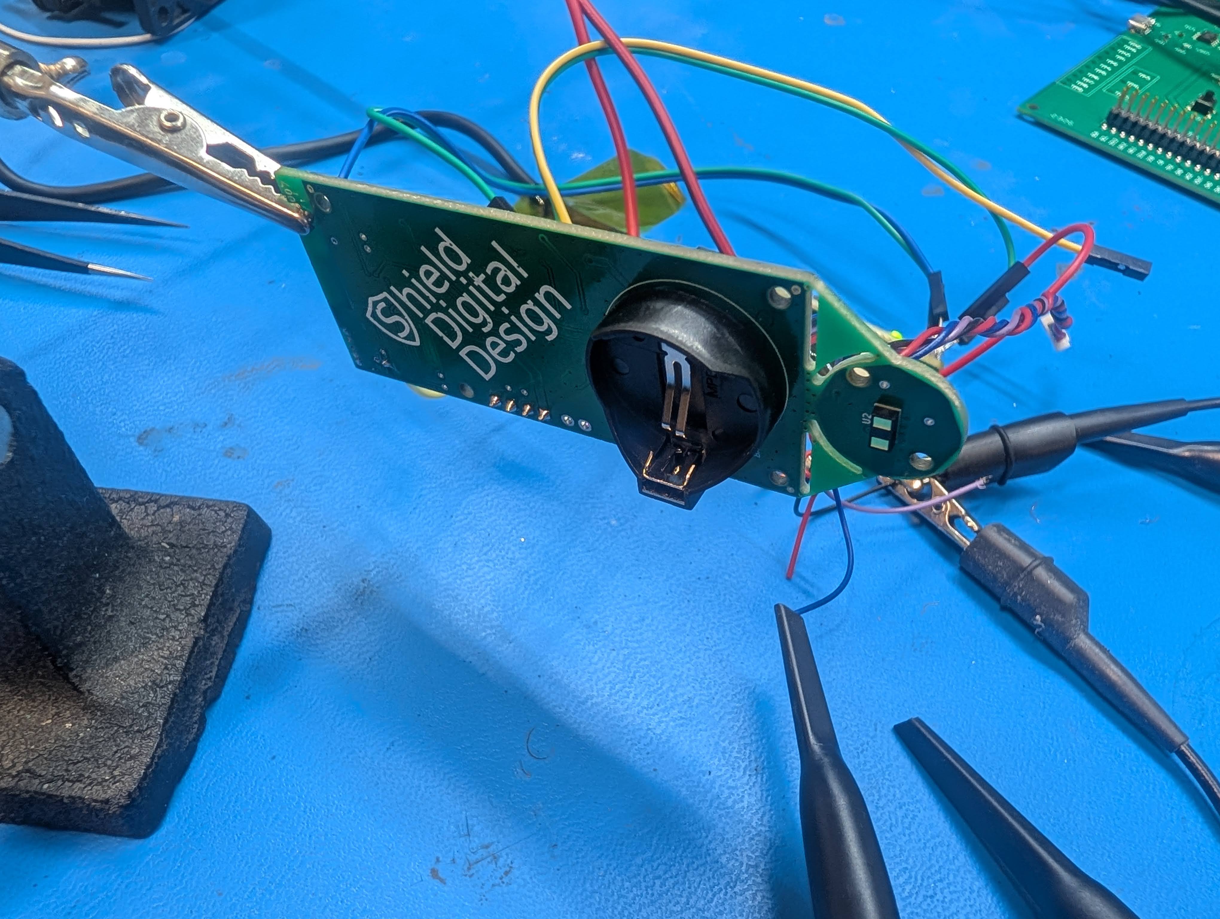
Unfortunately, the board sat on my shelf assembled and with a blinky firmware image programmed onto it until just this year.
That's when I discovered that I could direct some AI agents towards finally clearing the hurdle of finishing this project. My only alternative would have been to throw the board in the garbage, at this point. I was thrilled that, after connecting up a J-Link debugger, my agent could write firmware and flash the board on its own. Not only that, but it also took care of creating the Android application for my phone!
The bringup process wasn't without a few challenges, but they were not nearly as time-consuming as I expected. One particular issue: I had some SPI timing problems between the MCU and an RTC. I hooked up my Saleae logic analyzer and was pleasantly surprised to see that it had an MCP server available.
The Saleae logic analyzer and J-Link connected to the board during development. Notice that the ToF board has been disconnected from the main board and is now using the wire harness for data transfer.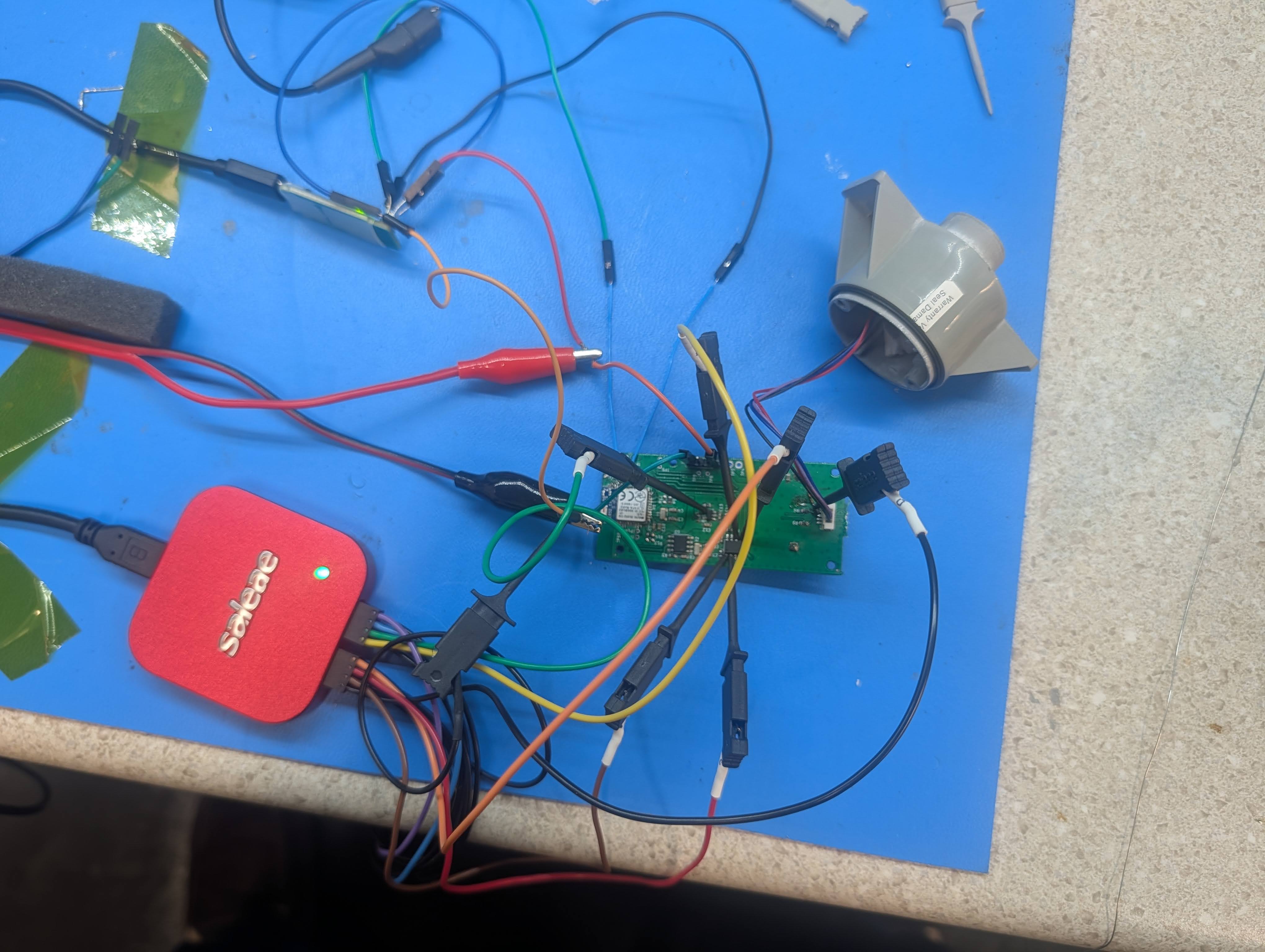
This resulted in a fascinating loop where the AI agent would write and flash firmware, capture SPI traces on the logic analyzer, then improve the firmware, in a completely self-contained process.
SPI interface capture from the logic analyzer. The VCC_EN and VCC_SW are showing my switched power rail (EN is the control signal, SW is the switched power rail itself being read from an analog input).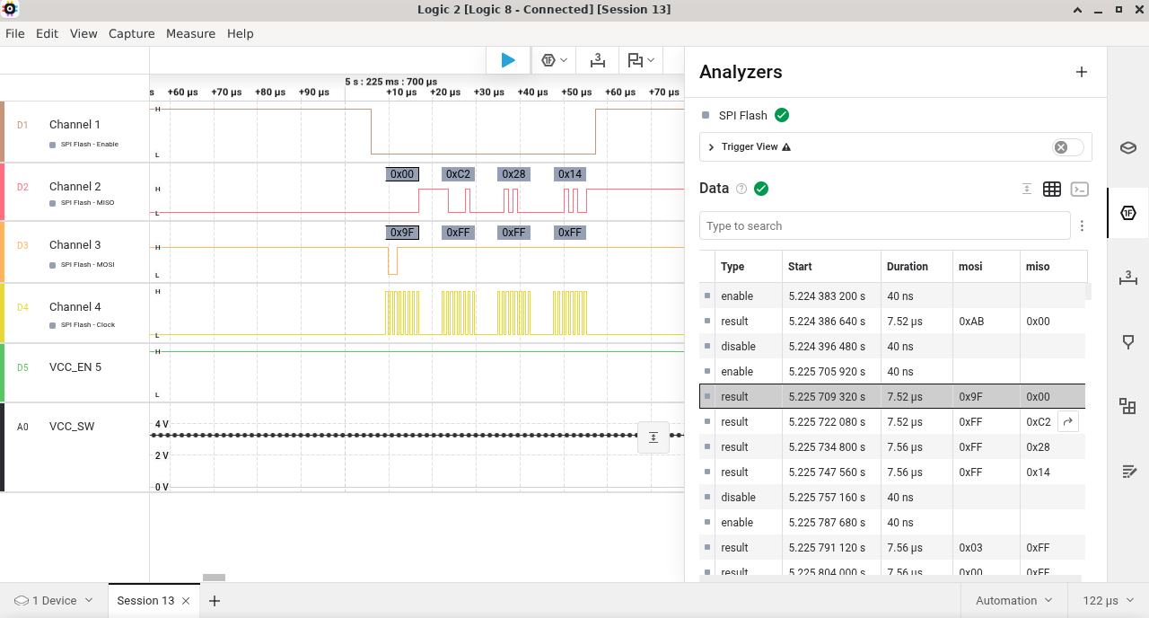
The firmware was designed to take a reading every four hours (reduced to every one hour when the level is low). It provides data graphs of the recorded data with the actual readings synced to the phone. I can also export the readings in CSV format so that I can keep my computer logs going.
The main screen of the Android application. It shows some characteristic AI verbosity but is overall quite usable.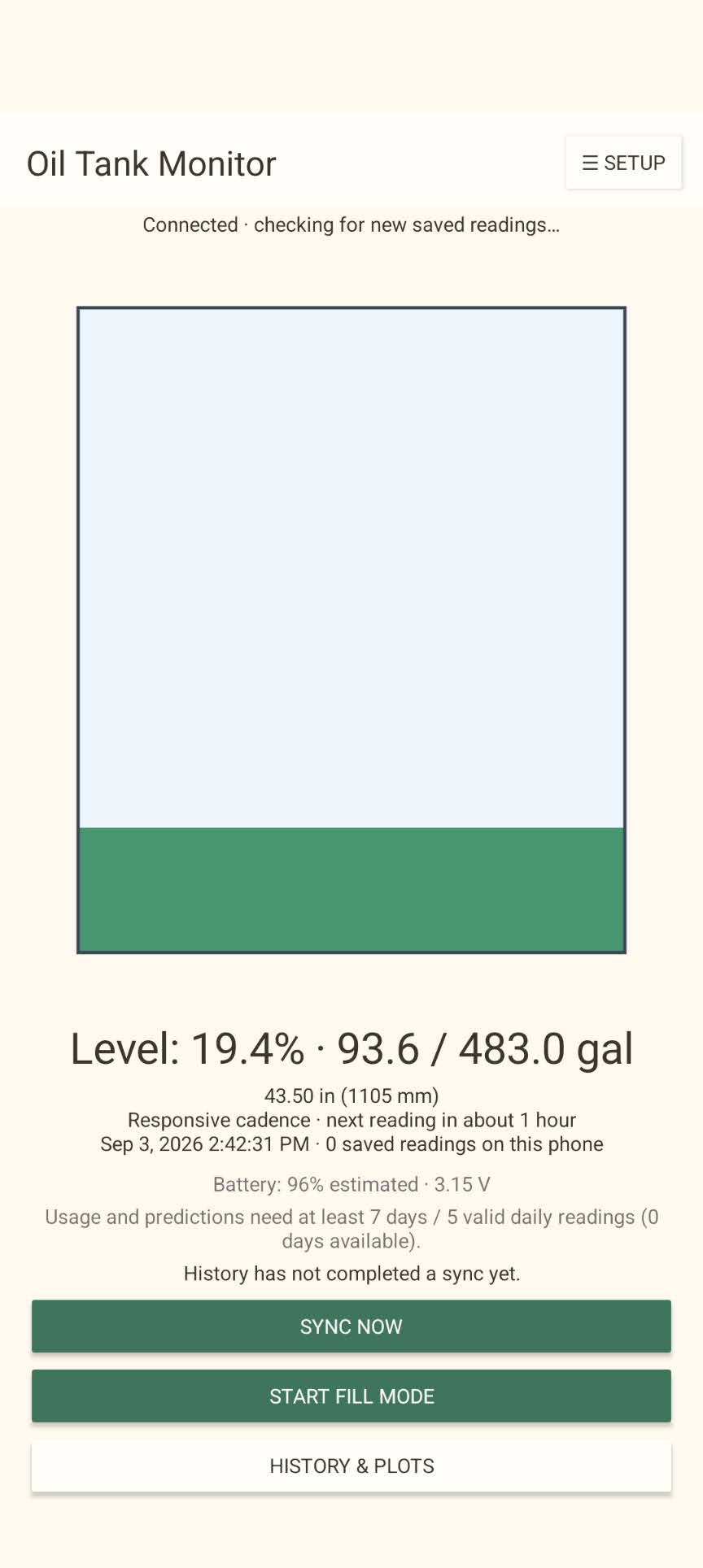
If I were making a general product, I would need to support many different tank sizes and configurations. In my case, I made the relation between distance reading and tank fill hard-coded to my own tank size.
The device installed and operating on my tank with the high-capacity 18650 battery installed.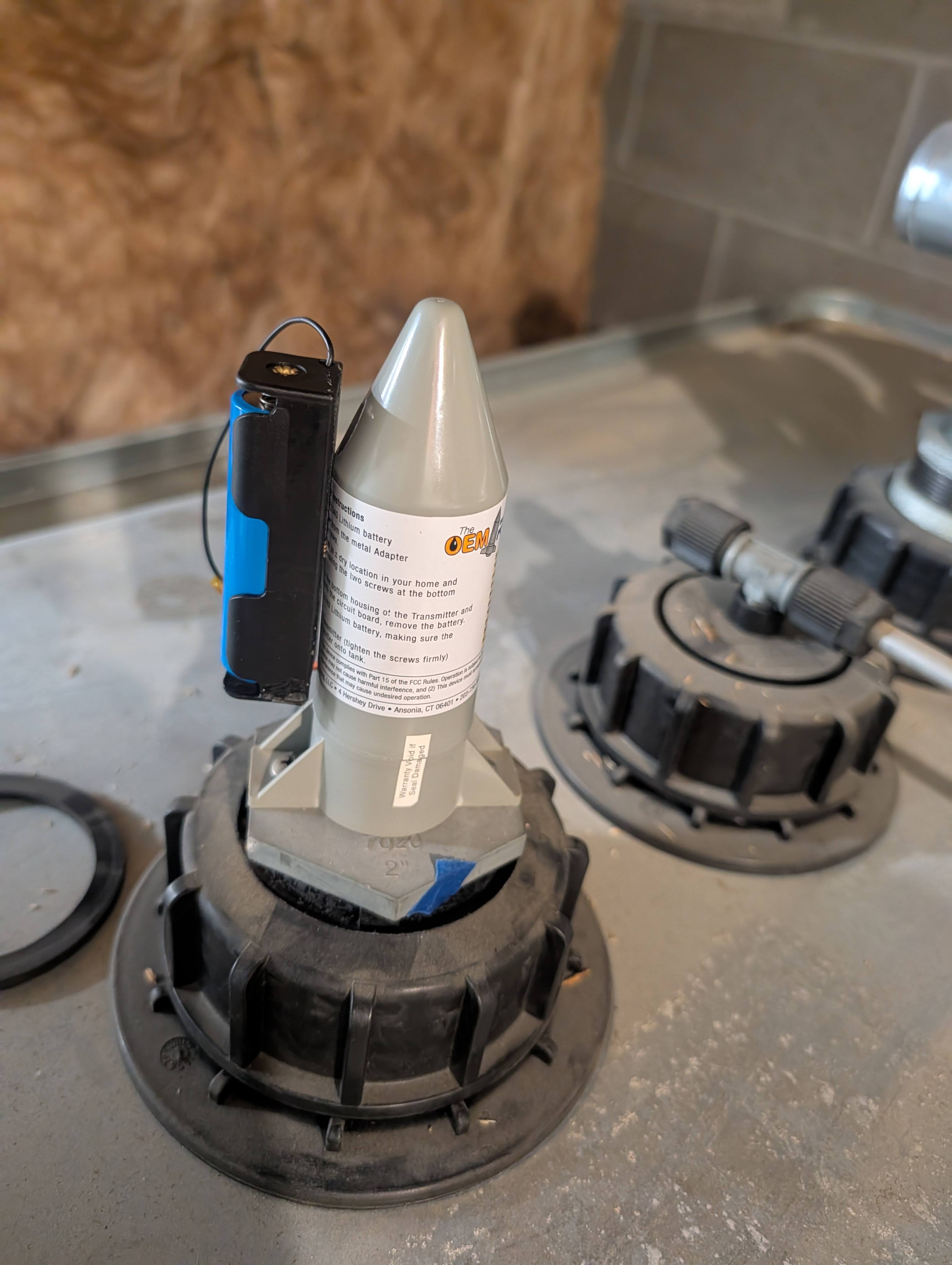
If you're interested in checking out the software repository for the project, here's a link:
Oil Tank Monitor
Many engineers are figuring out how to navigate our careers and hobbies in this new era of AI tools. I know that it is confusing to try and understand where we go from here with this hugely powerful tool, but I, for one, am completely embracing the ways AI and LLMs can save time while using them to propel my knowledge in the areas I'm personally passionate about.