The Quickest Antenna Design of the Year
Comments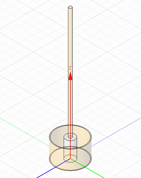
During a recent weekend, I found myself with some parts laying around which I hadn't used in quite a while. First in the bin was an old Orange Pi One1 (an underpowered SBC similar to the Raspberry Pi) which I was going to use to run a video conferencing screen but which proved to be unable to run the graphical Linux installation well enough to be usable. My RTL-SDR stick also happened to be out (I can't actually remember why I grabbed it a few weeks ago for the first time in years). As I cleaned everything up and got ready to put it away, I realized that I was probably never going to use this stuff again, so instead of trashing it I decided to put it to good use!
The Idea
I'm often interested in looking at real-time aviation data, especially when a plane or helicopter is flying nearby. I've even used my RTL-SDR to capture and decode ADS-B 2 packets in the past. This time, I decided to create a networked ADS-B receiver node and feed the data into websites such as Flightaware3 and Flightradar244. The only problem was, I did not want to spend a bunch of time on it - not much more than it would have taken to throw everything into the garbage!
Mechanical and Software Design
I knew that in an effort to minimize the installation time, this thing was going in the attic - no way was I going to expend the effort required to run cables outside the house nor entertain the idea of weatherproofing the device. I already had power available and a router with an open Ethernet port right in the middle of the middle of the attic (A consequence of running an old WRT54G with enough power to get Wi-Fi anywhere in my woods). Not only would time not permit me to run cabling external to the house, but until I petition for wifely approval of an antenna tower or convert a tall tree, there's no higher point to mount the antenna than the attic. One easy method to mount a bare PCB to the attic rafters was a 3D printed frame with points to screw the board in along with an almond-shaped hole to support the entire thing.
Figure 1. SBC mounting/hanging frame.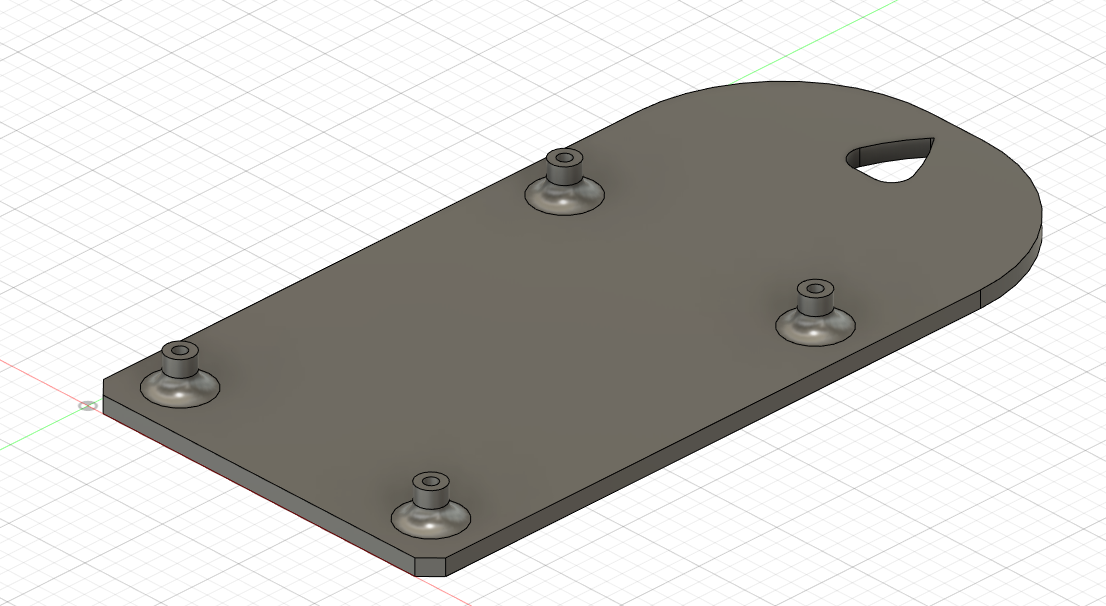
The software was one of the easiest parts thanks to the quick scripts available. The Orange Pi was running the latest Armbian in a headless, non-graphical mode. Both sets of instructions for Flightaware3 and FR244 were quick to configure. Since I saw a warning about high CPU temperature during bench testing, and because attic temperatures will be quite high, a quick and dirty heat sink consisting of thermal paste, pennies and super glue was constructed.
Antenna Design
Here's the part of the project where the Cadence Clarity 3D Workbench was so helpful. For the sake of simplicity, I realized that I could simply slide a piece of wire into the center conductor of the 75Ω coaxial connector. This would certainly prove to be the easiest (and quickest) method of finishing the project, and the results would be acceptable for my use-case. Additional care could be taken to improve the ground plane with radials extending out from the antenna, but that would detract from the speediness requirement.
Of course, we could use any quarter-wave vertical monopole calculator such as the number one result from Google5 which says to use a 2.6" wire for ADS-B's 1090 MHz frequency. I figured that without radials, I'd do my best to estimate the antenna properties into a 75Ω simulation port with the same geometry as the RTL-SDR 's coaxial connector. After some measurements with the calipers my base model was done in about 5 minutes.
Figure 2. Clarity 3D Workbench CAD model.
I started with the 2.6" recommendation from online calculators which showed the frequency was a tad bit too high. Two more iterations showed that 3" was the ideal length to extend from the coaxial connector. I pulled the bare center conductor from a piece of RG6 that was sitting on my bench, inserted it into the RTL-SDR , measured my 3" and cut.
Figure 3. Simulated antenna S11 amplitude.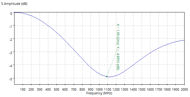
As a result of the fact that this quick and dirty antenna design had zero ground plane to speak of, it was obvious that we were never going to get anywhere near an ideal VSWR. As shown in Fig. 3 above, the return loss at resonance was about 5dB giving an SWR of around 3.5. In the future, a proper antenna design would certainly improve this but today's engineering trade-off valued time over performance.
Figure 4. 3D plot of antenna gain at operating frequency (dB).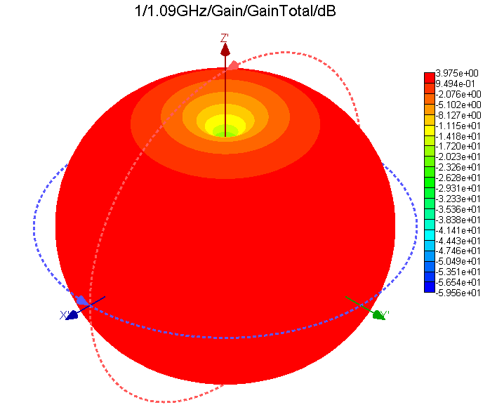
One final check in Clarity was to verify the far field radiation plot at 1090 MHz. The result was textbook for a quarter-wave monopole with a missing ground plane, and showed a peak gain of about 4dBi, which would certainly be higher with a better ground plane.
Installation and Performance
All that was left now was to put the system up in the attic. A climb up through the joists to the highest point within cabling distance of the router, then a quick nail is all that was needed. The final device mounting is shown below in Fig. 5 (but please excuse the photo quality - it was tough to get a decent shot while suspended on the joists with non-ideal lighting).
Figure 5. Attic installation of ADS-B receiver.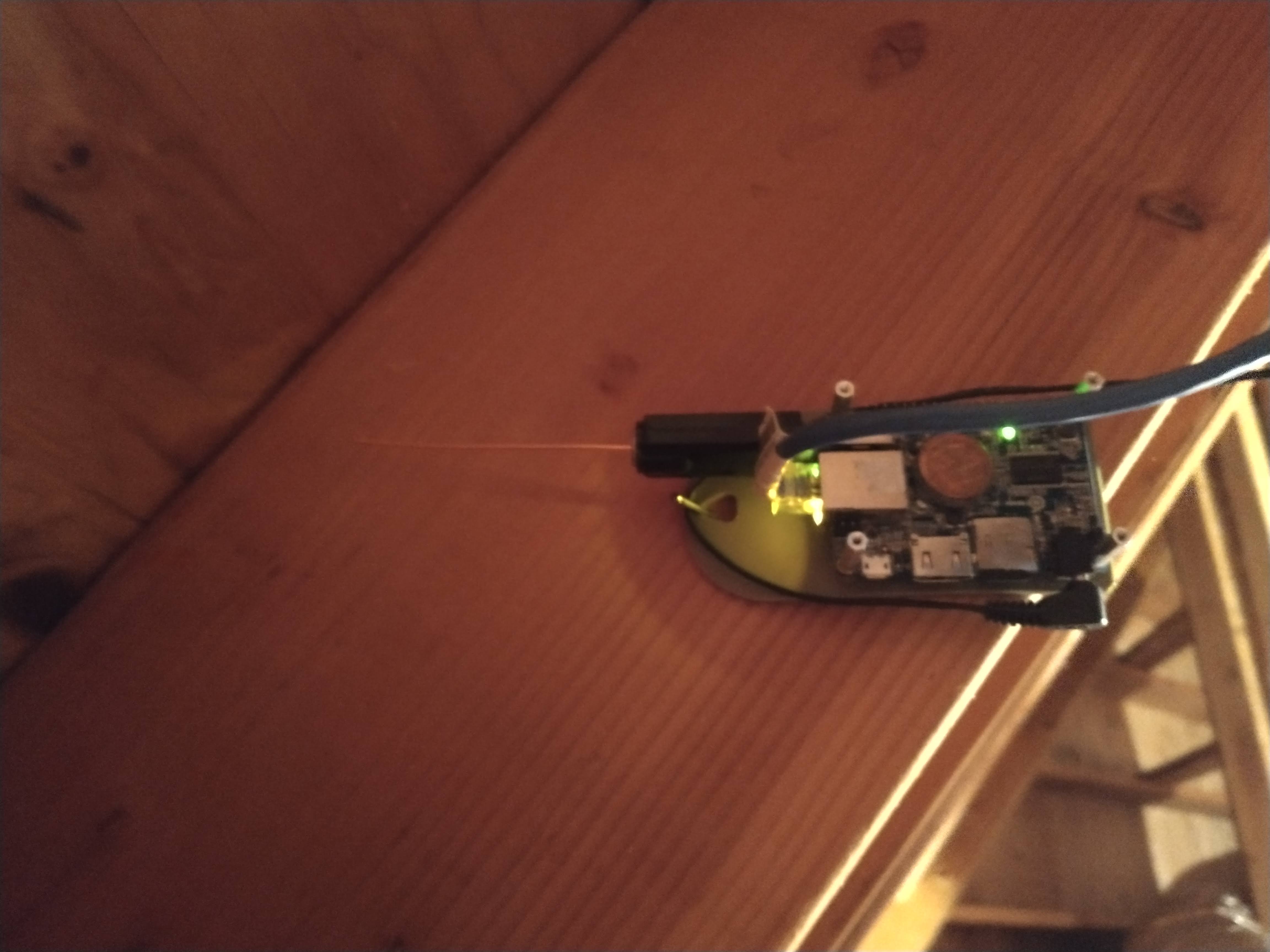
Upon plugging the device in and navigating to its internal web page (by default, available at "{ip address}:8080") it was encouraging to see some packets being received, with position data and everything! At least it worked enough to show basic functionality.
Figure 6. Real-time received ADS-B data.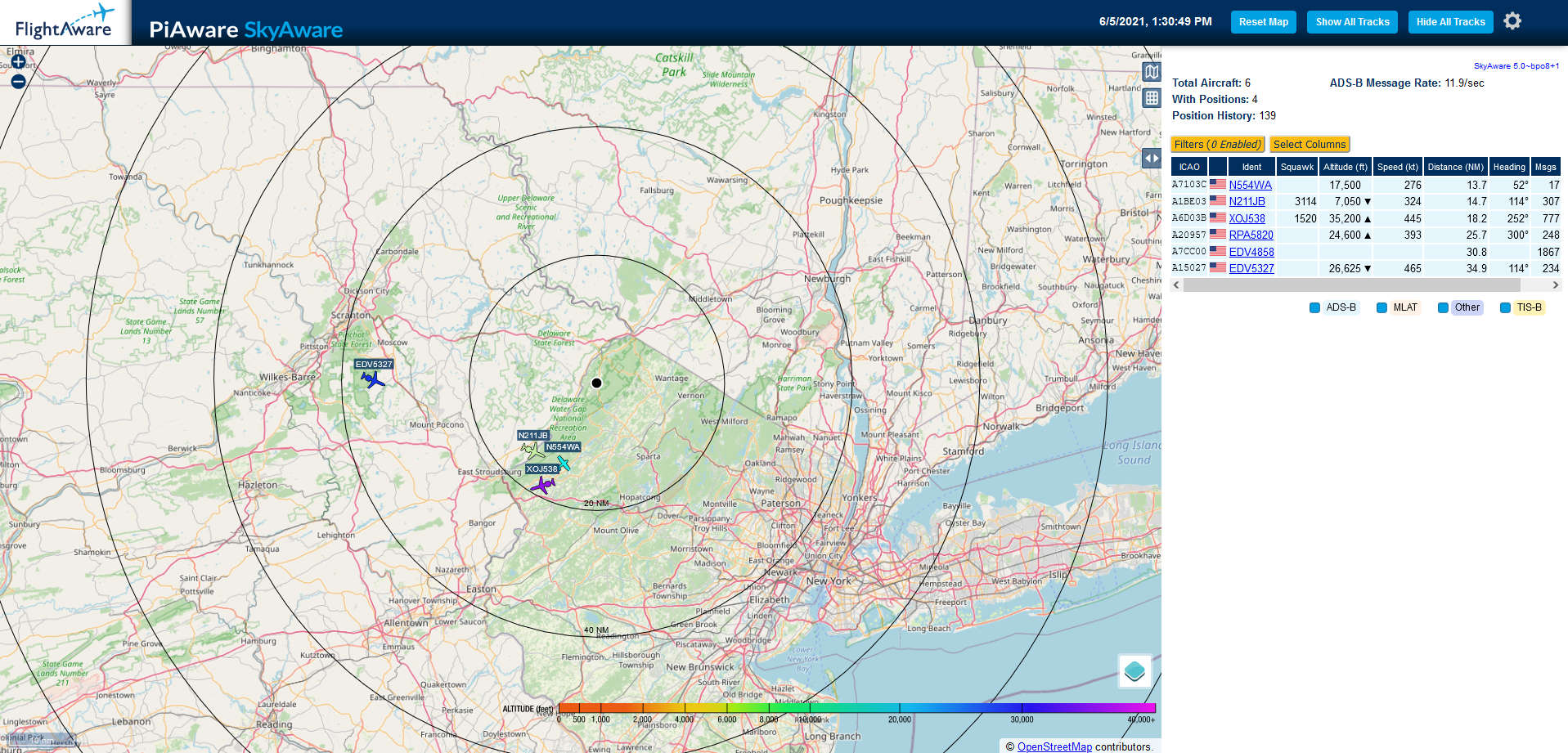
After watching the data for a few days, it was obvious that I was receiving packets much better from the West (especially Southwest). On one hand, it was obvious that the antenna design and location was not optimal (in addition to using what may be literally the cheapest 1090 MHz radio receiver ever). At the same time, I was receiving good data out to over 50 nm in the best directions.
Figure 7. ADS-B collected statistics showing range and direction of received data.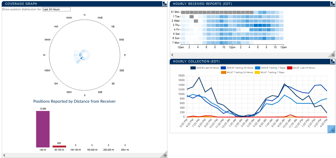
This leads me to one additional conclusion: the impact of the local geography. I'm situated just north of a long ridge which runs in a NE/SW direction. The ridge isn't terribly high, but it's high enough to be called "mountains"6 here in New Jersey. Closer still, I'm directly adjacent to a local peak which blocks essentially everything to my East. These issues could be mitigated somewhat with the aforementioned antenna tower, a better receiver or of course a better designed and mounted antenna. All things considered though, this project went from junk parts to working device in a matter of a couple of hours. Perhaps the antenna would be unnoticeably different had I just used a quarter-wave calculation instead of a field solver, but using Clarity 3D Workbench certainly added confidence that the final antenna length was ideal for this application. Like everything in engineering, this was a "cost, performance, time: pick two" situation and by that metric I'm extremely happy with the results.
Project File
If you'd like to play around with the design, the 3DEM file for use in Cadence Clarity 3D Workbench is available for download here:
Footnotes
Table of Contents
Related Engineering Insights
Parallel Plate Capacitor Equation - Simulated
The Question
A recent homework problem had us derive the parallel plate …
Webinar Recording: 6 Common SI/PI Issues Lurking in Your Design And How to Prevent Them
I recently presented a webinar with EMA Design Automation to explain some …
S-Parameters from a Neural Network
Continuing on the theme of using machine learning to speed up electromagnetic …
