The Mystery Misfire
Comments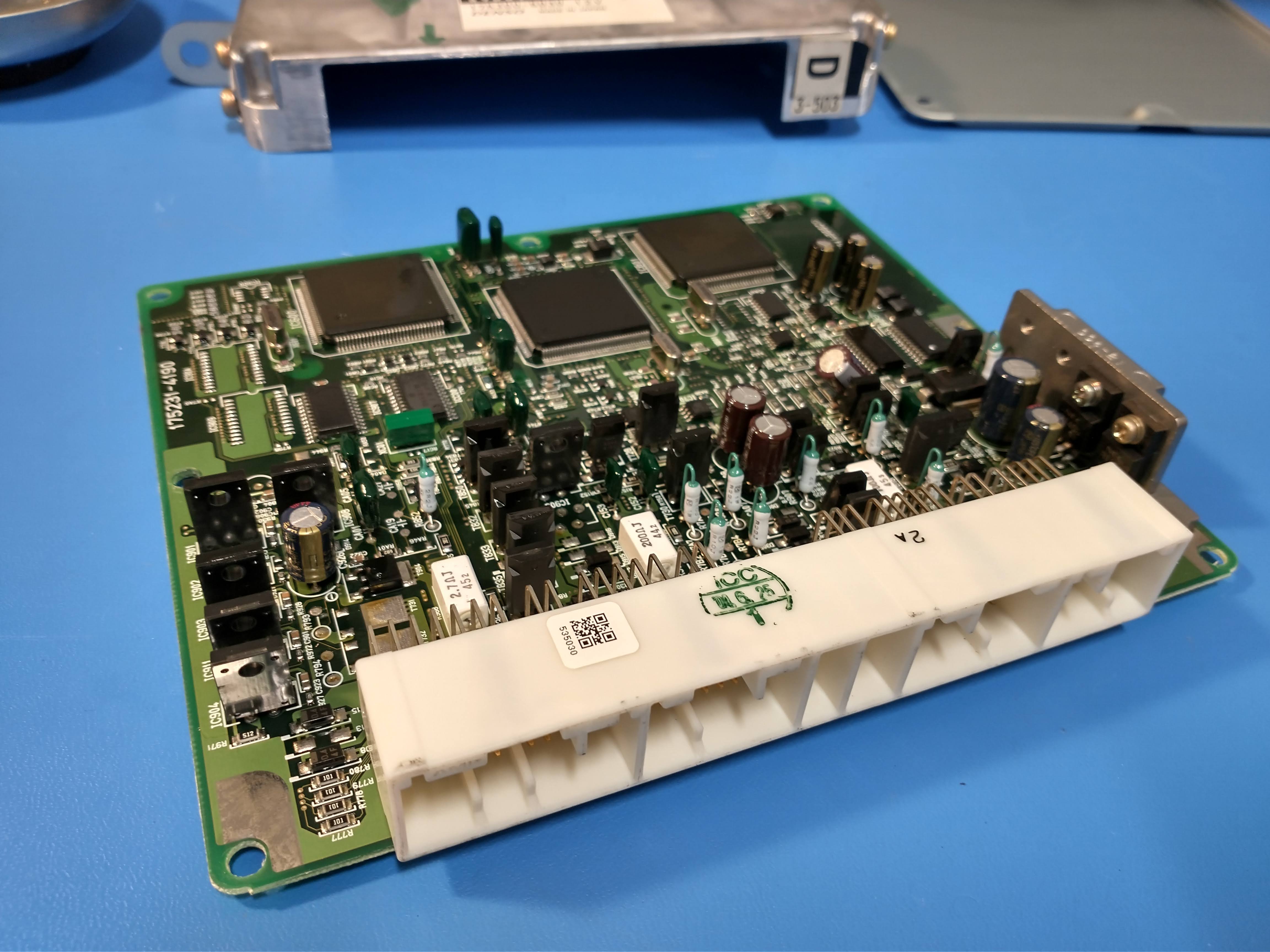
The dreaded P0171 code… If you've experienced it, just the mention likely gives you nightmares. If not - here's the rundown. P0171 is the automotive On-Board Diagnostics ( OBD ) code1 for a lean condition on the engine. If the engine is running lean, it simply means that the air to fuel ratio is not optimized, and there's either too much air or not enough fuel. Before I get too far ahead here, let's set the scene.
Routine Tune Up
We've all been there - time for a little routine maintenance on the car. Oil change, check the fluids and filters, basic tune up… oh and the last mechanic said the spark plugs need to be changed. No big deal, and hey - maybe this will get rid of the check engine light that's been on for the last year. That was the situation in the beginning, and there was certainly no cause for concern. The car was an '04 Celica belonging to a friend, and taking care of this work would certainly save him a few hundred bucks compared to taking it to a shop. The work went without a hitch, though right at the end while checking everything out I noticed there was a crack on the positive battery terminal and the connection was loose enough to warrant additional attention. In this case, we took the freshly tuned-up car on the 25 minute cruise to the nearest auto parts store and picked up a new terminal. Twenty-five minutes back home, and a few extra moments with a ratchet had the terminal firmly affixed to the battery. Little did we know, this was the start of our woes.
Our story’s 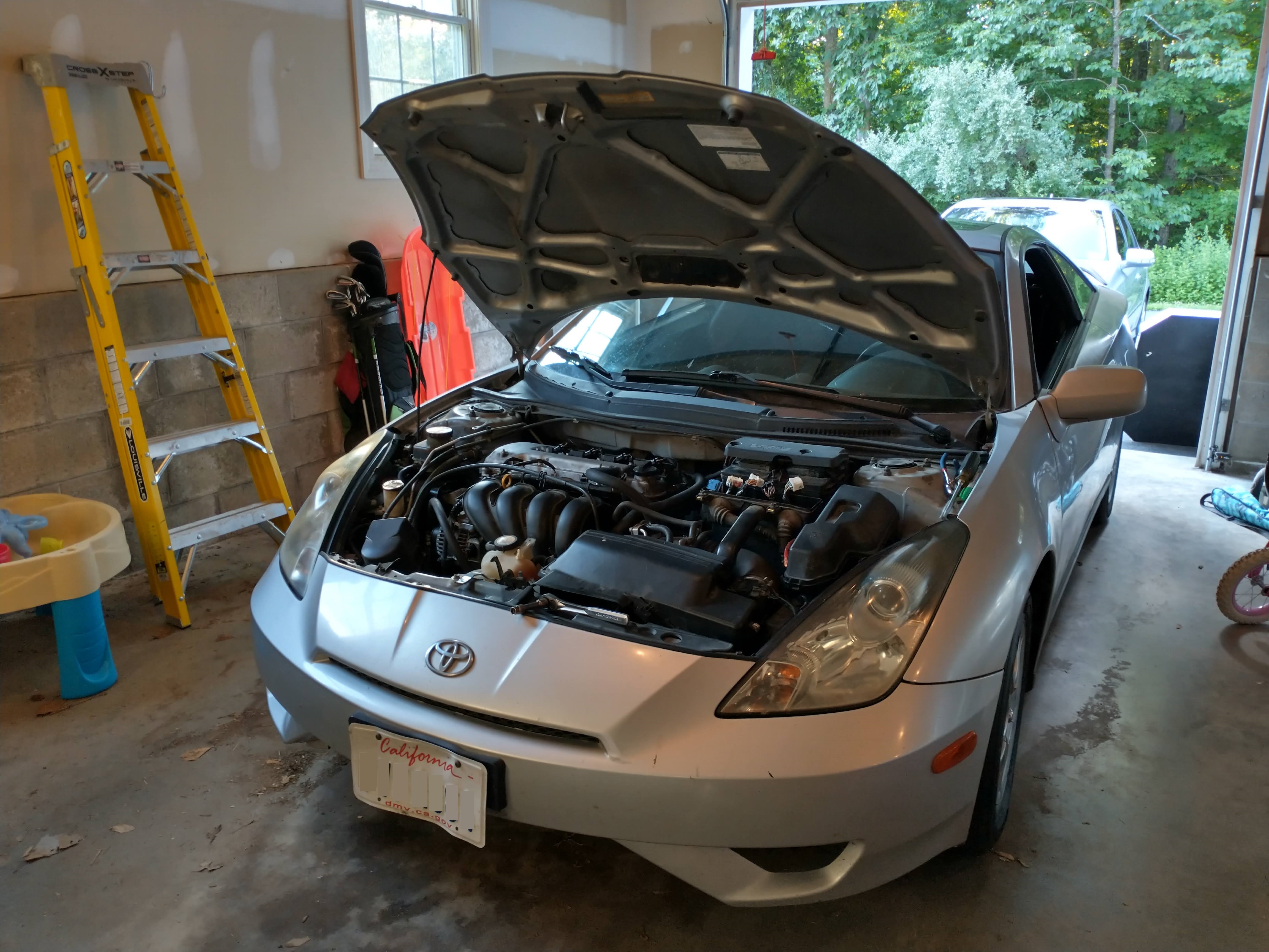
protagonist antagonist.
The Problems Begin
Upon starting the engine after replacing the terminal, and for a reason which is still a conundrum, the engine had a very rough idle and reported a misfire on cylinders 1 and 2. The car gave a lean code as well, but we were told this code had been there all year so likely could be safely ignored. Assuming the lean condition contributed nothing to our current woes, we did what normally would be done for a misfire… swapped coils around, swapped spark plugs, anything that could be related to the work we had done earlier in the day. We even tried a procedure to run the ECU 2 through the "relearn" phase, a reset of sorts. The true riddle here is why the misfire only began after changing the battery terminal (which really should have no effect at all).
Continuing to focus on the misfire code, we ordered new coils (no change). Next we checked the cylinder compression, just in case there was a bent valve (no issue). At this point it dawned on us: perhaps the lean code was related. If the air/fuel mixture really were off enough, it could cause the misfires to occur. Thanks to the kind folks at celicahobby.com.3 we were able to snag the Toyota service manual for the car and follow their recommended troubleshooting steps.
Checking Everything
At this point, it was time to follow Toyota's recommended procedures for misfires and lean codes. The mass air flow sensor was checked (resistance when off and voltage when on). No issues were to be found and the part looked recently replaced. Following that theme, we followed a few more intake-related thoughts. we sprayed intake cleaner in the hopes that the solvent would wash away dirt. we checked for a vacuum leak (including the effort of making a DIY smoke tester).4 For anyone curious, the smoke tester worked wonderfully but the lack of vacuum leak means we had to move on to the next step.
Quite often when working on my 2-stroke lawn equipment, I use starting fluid to troubleshoot things or ya know start the engines. I had the same thought here, let's spray some starting fluid down the intake and see what happens. In honor of Dr. Bogatin's rule #9,5 I made some pre-conceived expectations about what was going on. If the engine bogs down, then there's adequate fuel getting to the combustion chambers and we still need to find the air deficiency. Conversely, if the engine revs up we know that there's a legitimate lack of fuel.
As it turns out, the starting fluid caused the engine to roar to life. We were able to focus our energy on the fuel side of the air/fuel ratio. There's really not much in the fuel system - a pump, filter and injectors . Given the sunk cost of our time which has already been devoted to the issue (compared to the relatively low cost of the parts); we went ahead and ordered all of those parts. Starting at one end, the new pump and filter were replaced. One short test drive later and it was apparent that we were still no closer to a solution.
Success?
That left the injectors. If these didn't help, we were ready to junk the car (and seriously regretting being observant enough to catch the cracked battery terminal). After a few short minutes, the new injectors were in and we were ready to start it up. It took us by surprise to hear the engine rev up to a healthy RPM. Could this really have been it? Just clogged injectors? I took the car on another test drive down my beautiful, rural Sussex County roads hoping it didn't break down on me. I'm not sure if I was more worried about the time it would take a tow truck to get to me, or if a bear would sense my vulnerability and pay me a visit.
Fortunately, there were no bears or tow trucks encountered. Less fortunately, the car ran great at low speeds but still had an obvious stutter at high speeds. It was good enough to drive around a bit, but not quite good enough to call the problem solved. Upon returning to the garage, we discovered a misfire on cylinder 2, but we were quite convinced it was still injector related. Yet another trip through the Toyota service manual pointed us in the right direction.
Oscilloscope in the Garage: Critical Tool?
The service manual provides a reference waveform for measuring the injector control signal from the ECU . An inspection of the waveform and realizing that the two wires going to the injector are +12V and the control signal was a dead giveaway that the ECU was using an open-collector driver6 to control these.
Figure 1. Toyota’s reference injector signal waveform.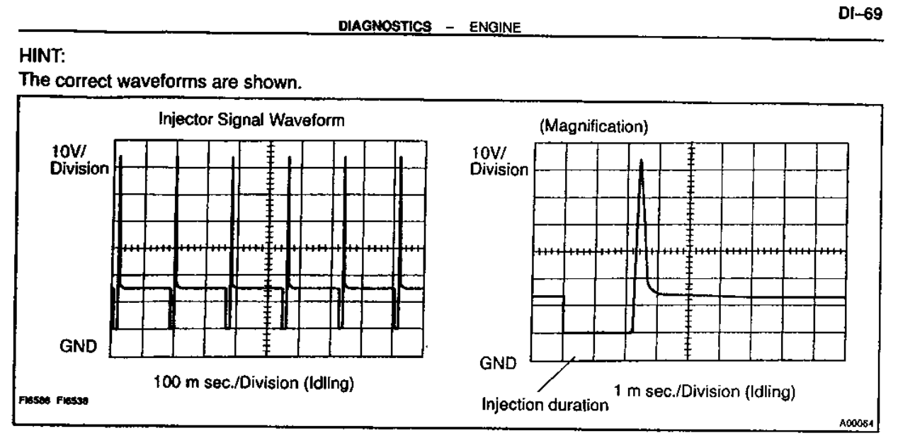
I'll never give up an opportunity to use my 'scope for troubleshooting, so we brought it out and hooked it up. Turns out we were on to something. The other cylinder measurements were right in line with the reference waveform but cylinder 2 was just a solid low voltage with no pulses.
Figure 2. Measurement on a good injector.
Since each injector had good resistance across its coil (spec is about 14Ω) we were quite sure that there was an ECU issue. We started out checking prices on an entire ECU module… which were no cheaper than $400! The goal here was to get this car fixed quickly (well, that was out the window by now) or at least cheaply. Since I was pretty sure the driver was an open-collector BJT ,7 I thought I'd crack open the ECU and check it out.
Figure 3. Engine bay with ECU removed.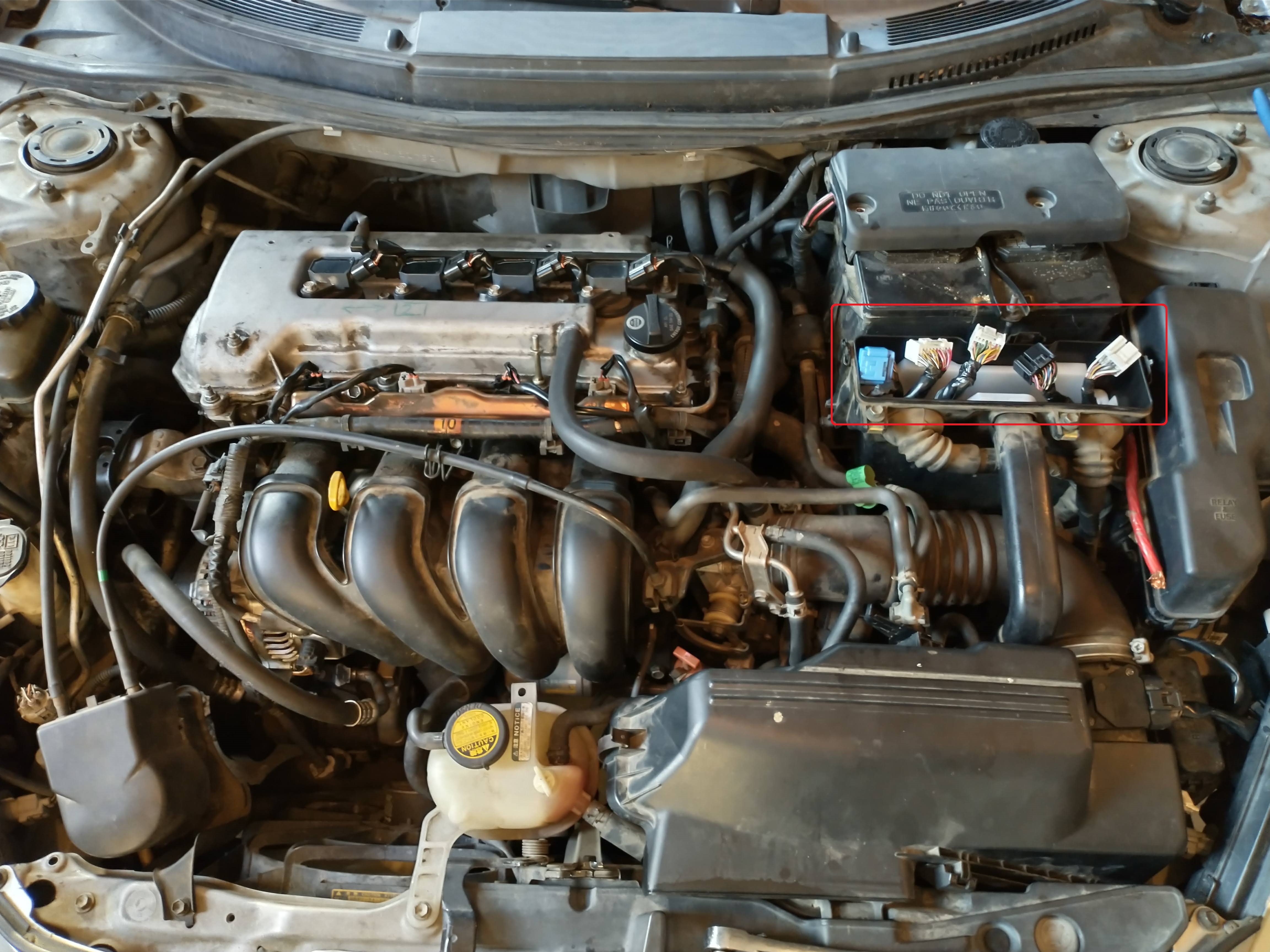
Figure 4. ECU after removal with injector #2 pin marked.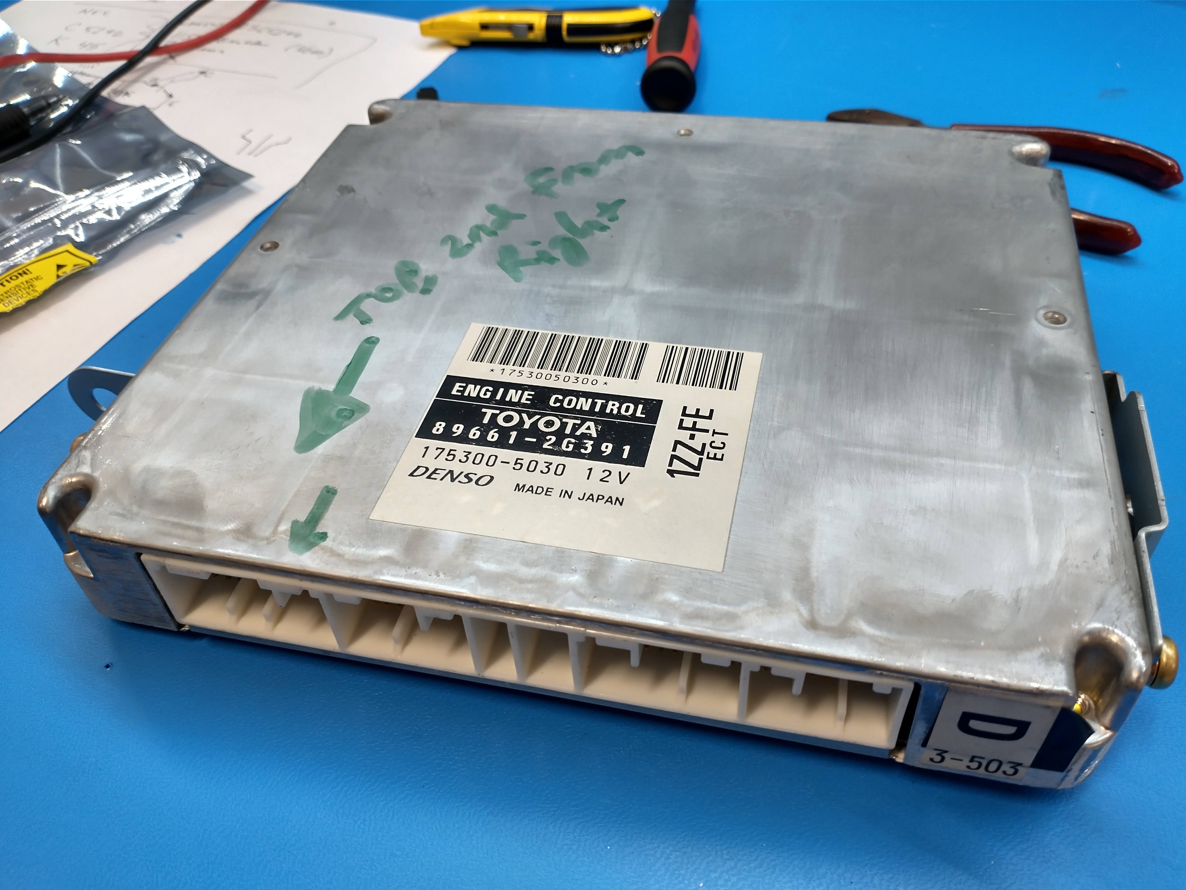
Figure 5. ECU printed circuit board.
Using a multimeter , it was a quick endeavor to find the failed BJT . Additionally, inspecting the layout and pin configuration made it easy to figure out which pin was which. Two pins on this transistor were measuring a dead short while the part was in-circuit, which was significantly different than the drive transistors for the other three injectors . The short was confirmed after the transistor was removed.
Figure 6. ECU PCB with failed BJT pointed out.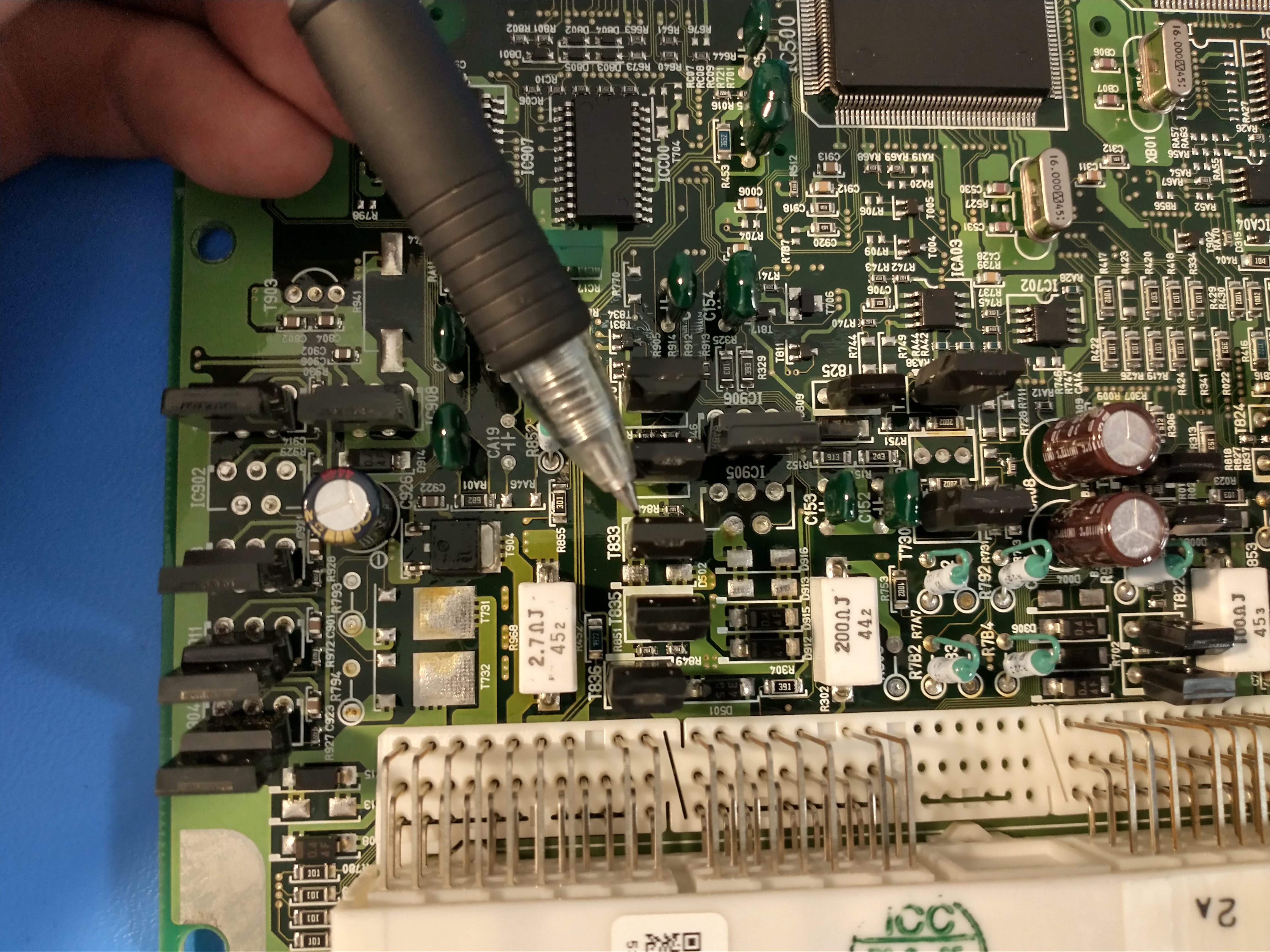
At this point, a suitable replacement was needed. While the pin configuration was known, the critical part ratings were not. This transistor was being used as a switch, so it wasn't important to look at AC/small-signal performance, but we do know it needs to sink about 850mA at steady state (the +12V divided by the 14Ω coil resistance). We also are not sure what kind of maximum voltages we need to endure, but it's likely to be at least 65V based on the reference waveform. The part had NEC markings, and after some research we discovered that NEC's semiconductor division was sold to Renesas . While Renesas was eventually very helpful, we went ahead and ordered a part that we thought would meet the needs of the circuit before we had a chance to hear back from them. After a few days waiting for the Digi-key order to arrive, we were ready to resume work on the car.
Figure 7. ECU with new BJT installed.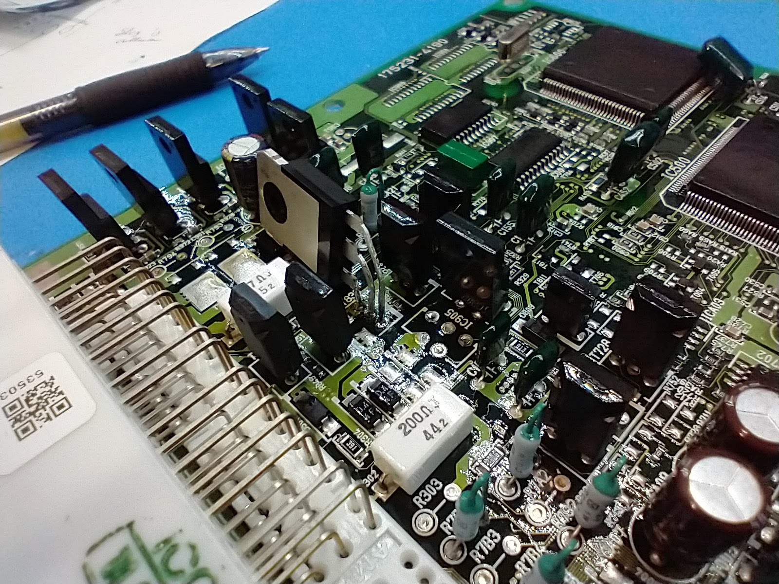
As it turns out, we probably over-estimated the needed specifications when we ordered the ON Semiconductor 2SC5242OTU,8 which was rated for 250V and 17A. A bit of creative lead-bending and we had it in there. We had to install it with a 90deg tilt so that there was enough clearance to fit the board within the enclosure. Lastly, there was a bit of worry that the heavier part might have vibration issues, so a heavy staking with hot glue gave some extra insurance.
Figure 8. New transistor after installation and staking.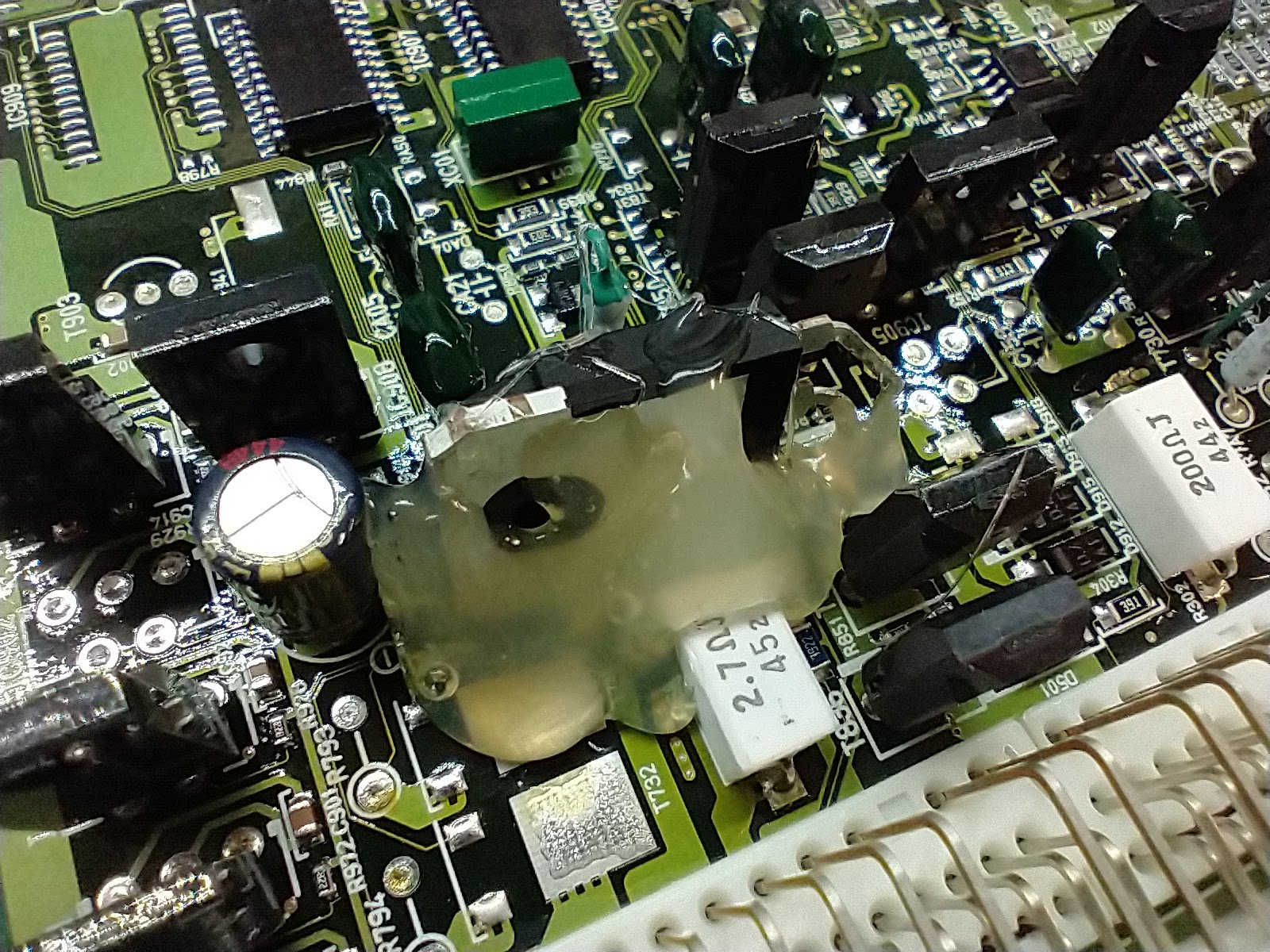
That should do it, right? We installed the ECU in the car and were ready to get this car back on the road with a whole new enthusiasm.
Engineering can't Explain Everything
We had a saying in the Coast Guard when we couldn't explain why something started or stopped working for no reason, despite our best efforts: PFM.9 It was at this point where we encountered the phenomenon on the Celica. After all that effort, the misfire on cylinder 2 was gone, but a new one appeared on #1. It felt like we were back to the drawing board. Unplugging the injector control signal did nothing to change the rough idle, indicating that either this injector's signal was not present or the injector itself was bad (but how could that be, it was brand new). We re-opened the ECU to verify there were no shorts on the #1 output drive transistor (good), checked the signal on the #1 injector (good), and pulled the valve cover and verified valve clearances were in spec (good). Back to the service manual for some sanity, we re-followed the instructions despite how useless they seemed. This included checking the coil resistance which shouldn't be an issue on a brand new injector. Turns out at some point between the last run and this run, the #1 injector coil went open circuit!
Figure 9. Fuel injector cleaning and testing setup.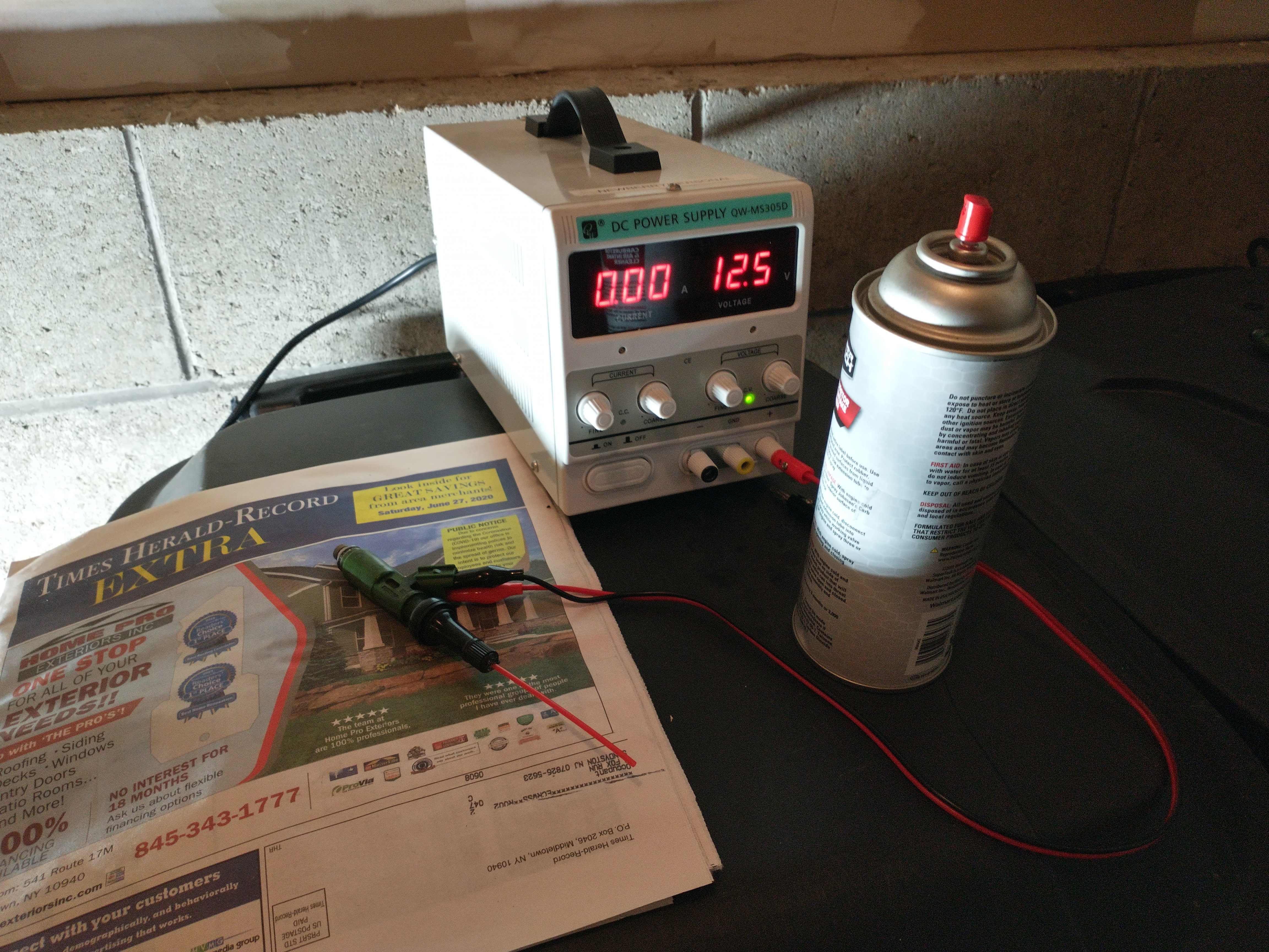
In an attempt to get things going quickly (still futile) we took an old injector and attempted to clean it out. This was a two-person job with some custom tools. A spare valve stem happens to fit perfectly over the rail-side of the injector. A small hole bored in the top of the valve cap allowed the straw from the intake cleaner can to form this part of our setup. A DC power supply capable of sourcing about 1A was set for 12.5V output and connected to the injector via alligator clips. Here's where the 2nd person comes in: one person quickly sprays spurts of intake cleaner in the top end of the injector while the other person quickly cycles power to the injector by repeatedly contacting the banana plug to the power supply to simulate the ECU's drive signal. This procedure did work to get a nice spray pattern from the old injector but fair warning: don't let the intake cleaner pressure build up too high without cycling power to the injector or the custom valve stem adapter is liable to pop off violently.
Victory… Finally
While we were hopeful, the old-but-cleaned injector was just not enough to get rid of the rough idle. A warranty claim on the failed new injector and a few more days waiting for the part to arrive ultimately eliminated this lean code once and for all.
So, what is the ultimate takeaway from this story? I would hope that it provides a bit of a guide for someone dealing with a similar situation. More specifically, it's not always necessary to replace the expensive electronics modules in a car when often just one component needs rework. In this case, a seemingly innocuous and generic trouble code was the result of a single failed circuit component that could be had for $3.
